- 您现在的位置:买卖IC网 > Sheet目录514 > SIHG20N50C-E3 (Vishay Siliconix)MOSFET N-CH 500V 20A TO247
Package Information
www.vishay.com
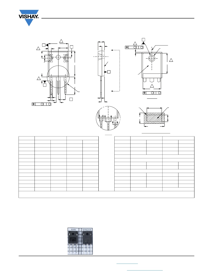
TO-247AC (High Voltage)
Vishay Siliconix
4
A
A
B
3 R/2
E
E/2
S
A2
A
7 ?P
? k M D B M
(Datum B)
?P1
Q
D2
2xR
(2)
D
4
D1
4
1
2
3
D
Thermal pad
4
5 L1
C
L
4
See view B
A
E1
0.01 M D B M
2 x b2
3xb
0.10 M C A M
b4
2x e
A1
C
Planting
V iew A - A
(b1, b3, b5)
Base metal
Lead Assignments
1. Gate
D DE
E
2. Drain
3. Source
4. Drain
C
C
(c)
c1
(b, b2, b4)
(4)
View B
Section C - C, D - D, E - E
MILLIMETERS
INCHES
MILLIMETERS
INCHES
DIM. MIN. MAX.
A 4.58 5.31
A1 2.21 2.59
A2 1.17 2.49
b 0.99 1.40
b1 0.99 1.35
b2 1.53 2.39
b3 1.65 2.37
b4 2.42 3.43
b5 2.59 3.38
c 0.38 0.86
c1 0.38 0.76
D 19.71 20.82
D1 13.08 -
MIN. MAX.
0.180 0.209
0.087 0.102
0.046 0.098
0.039 0.055
0.039 0.053
0.060 0.094
0.065 0.093
0.095 0.135
0.102 0.133
0.015 0.034
0.015 0.030
0.776 0.820
0.515 -
DIM.
D2
E
E1
e
?k
L
L1
N
?P
? P1
Q
R
S
MIN. MAX.
0.51 1.30
15.29 15.87
13.72 -
5.46 BSC
0.254
14.20 16.25
3.71 4.29
7.62 BSC
3.51 3.66
- 7.39
5.31 5.69
4.52 5.49
5.51 BSC
MIN. MAX.
0.020 0.051
0.602 0.625
0.540 -
0.215 BSC
0.010
0.559 0.640
0.146 0.169
0.300 BSC
0.138 0.144
- 0.291
0.209 0.224
0.178 0.216
0.217 BSC
ECN: X13-0103-Rev. D, 01-Jul-13
DWG: 5971
Notes
1. Dimensioning and tolerancing per ASME Y14.5M-1994.
2. Contour of slot optional.
3. Dimension D and E do not include mold flash. Mold flash shall not exceed 0.127 mm (0.005") per side. These dimensions are measured at
the outermost extremes of the plastic body.
4. Thermal pad contour optional with dimensions D1 and E1.
5. Lead finish uncontrolled in L1.
6. ? P to have a maximum draft angle of 1.5 to the top of the part with a maximum hole diameter of 3.91 mm (0.154").
7. Outline conforms to JEDEC outline TO-247 with exception of dimension c.
8. Xian and Mingxin actually photo.
Revision: 01-Jul-13
1
Document Number: 91360
For technical questions, contact: hvm@vishay.com
THIS DOCUMENT IS SUBJECT TO CHANGE WITHOUT NOTICE. THE PRODUCTS DESCRIBED HEREIN AND THIS DOCUMENT
ARE SUBJECT TO SPECIFIC DISCLAIMERS, SET FORTH AT www.vishay.com/doc?91000
发布紧急采购,3分钟左右您将得到回复。
相关PDF资料
SIHG24N65E-E3
MOSFET N-CH 650V 24A TO247AC
SIHP12N60E-E3
MOSFET N-CH 600V 12A TO220AB
SIHP30N60E-E3
MOSFET N-CH 600V 29A TO220AB
SIHP5N50D-E3
MOSFET N-CH 500V 5.3A TO220AB
SIHP6N40D-E3
MOSFET N-CH 400V 6A TO-220AB
SIHP7N60E-GE3
MOSFET N CH 600V 7A TO-220AB
SIHU3N50D-E3
MOSFET N-CH 500V 3A TO251 IPAK
SIHU5N50D-E3
MOSFET N-CH 500V 5.3A TO251 IPAK
相关代理商/技术参数
SIHG22N50D-E3
功能描述:MOSFET 500V 22A 312W 230mOhm @ 10V
RoHS:否 制造商:STMicroelectronics 晶体管极性:N-Channel 汲极/源极击穿电压:650 V 闸/源击穿电压:25 V 漏极连续电流:130 A 电阻汲极/源极 RDS(导通):0.014 Ohms 配置:Single 最大工作温度: 安装风格:Through Hole 封装 / 箱体:Max247 封装:Tube
SIHG22N50D-GE3
功能描述:MOSFET 500V 230mOhm@10V 22A N-Ch D-SRS
RoHS:否 制造商:STMicroelectronics 晶体管极性:N-Channel 汲极/源极击穿电压:650 V 闸/源击穿电压:25 V 漏极连续电流:130 A 电阻汲极/源极 RDS(导通):0.014 Ohms 配置:Single 最大工作温度: 安装风格:Through Hole 封装 / 箱体:Max247 封装:Tube
SIHG22N60E
制造商:VISHAY 制造商全称:Vishay Siliconix 功能描述:E Series Power MOSFET
SIHG22N60E_13
制造商:VISHAY 制造商全称:Vishay Siliconix 功能描述:E Series Power MOSFET
SiHG22N60E-E3
功能描述:MOSFET 600V 180mOhm@10V 21A N-Ch E-SRS
RoHS:否 制造商:STMicroelectronics 晶体管极性:N-Channel 汲极/源极击穿电压:650 V 闸/源击穿电压:25 V 漏极连续电流:130 A 电阻汲极/源极 RDS(导通):0.014 Ohms 配置:Single 最大工作温度: 安装风格:Through Hole 封装 / 箱体:Max247 封装:Tube
SIHG22N60E-GE3
功能描述:MOSFET 600V 180mOhm@10V 21A N-Ch E-SRS
RoHS:否 制造商:STMicroelectronics 晶体管极性:N-Channel 汲极/源极击穿电压:650 V 闸/源击穿电压:25 V 漏极连续电流:130 A 电阻汲极/源极 RDS(导通):0.014 Ohms 配置:Single 最大工作温度: 安装风格:Through Hole 封装 / 箱体:Max247 封装:Tube
SIHG22N60E-GE3
制造商:Vishay Siliconix 功能描述:MOSFET N CH 600V 21A TO-247AC-3
SiHG22N60S
制造商:Vishay Semiconductors 功能描述:
